Program

Programming our robot was the biggest challenge. After a lot of trial and error, we figured out that our problem in the program was that we had the motors inside the gray box. This made it so it would not work for both of the true and false portions, and our robot would only turn in circles. After moving the motors to the outside of the gray box (shown in the program above) it includes it in both the true and false cases. After we made this change, we had a working program that allowed our robot to follow the line successfully.
Schematic Editor

This is our schematic editor. We had a light sensor, sonic sensor, two motors, and two motor controllers. In this, the light sensor was told to determine the value of the black line and compare this value to the program, making the statement either true or false. Our motors were each set to 100% power level (one negative and one positive) in order for the robot to go straight at its highest speeds. All of our wires on our robot were connected to the motor controllers.
Line Follower Prototype
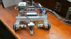
This is our first and only prototype that we built for this design challenge. We were able to get this design by directions given to us. It includes a sonic sensor, light sensor, two motors, and a stable structure that made it successful. The light sensor is close to the ground and in the front of the robot which reads the values underneath it, deciding whether it fits the true or false on our program following the black line.
Light Sensor

The light sensor is placed low to the ground, infront of the robot in order to read the values of the black line underneath. The readings then determine if our program statement should be true or false at the moment. Depending on which statement it is, decides which motors turn off and on.
Battery
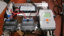
The battery on the top middle of our robot gives our robot the power to move, being our robots source of power and energy. During this challenge it seemed like we had to charge our battery multiple times, taking up time that we could have been testing it. Next time, we can try to figure out a way to perserve the energy better.
Underneath Structure
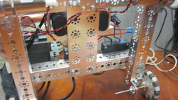
This the bottom of our robot. It shows the sturdy underneath structure that supported our robot in this design. The wheels towards the back were not attached to any motors, although still had a big part in supporting our robot as a whole.
Motors
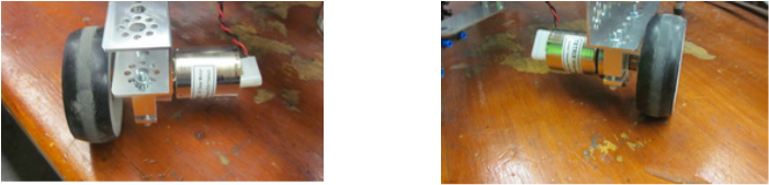
On our robot we had two motors. One on the right and one on the left, which allowed our robot to move. These motors were told to either turn on or off depending on the light sensors value and communication with the program. Doing this, it was able to stay following the black line successfully.
